High-Density Data Center Risk: Engineering Implications of Liquid Cooling, Lithium-Ion UPS Systems, and On-Site Power
As high-density AI and HPC workloads accelerate, traditional property loss prevention models must adapt. Localized coolant releases, lithium-ion thermal runaway, and microgrid control dependencies create multi-system common-mode risks. Learn how to evaluate liquid cooling, energy storage, and on-site generation through functional redundancy and FM Data Sheet 5-32 loss prevention standards.
Executive Summary
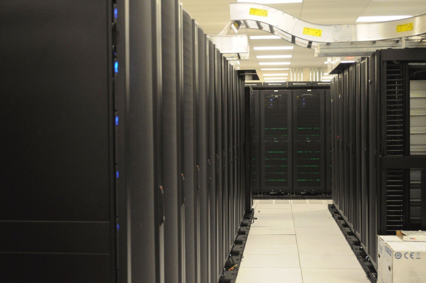
High-density artificial intelligence and high-performance computing facilities are changing how property losses can develop and spread across data centers. Liquid cooling places fluid distribution equipment close to critical servers and electrical systems. Lithium-ion uninterruptible power supply systems introduce thermal-runaway, off-gas, and re-ignition hazards. On-site generation and microgrids create new dependencies among fuel, electrical, cooling, and control systems.
These technologies should not be evaluated as isolated equipment additions. A localized coolant release, battery failure, electrical fault, or control-system event can affect several systems at once. The central property loss prevention question is whether a credible failure can be detected, isolated, and recovered without disabling redundant capacity.
FM Property Loss Prevention Data Sheet 5-32, Data Centers and Related Facilities, provides the primary property-conservation framework for this review.[1] Applicable codes, equipment listings, and Authority Having Jurisdiction approval remain essential, but code compliance alone does not establish protection against a severe property or business-interruption loss.
These changes build on the broader data center loss-prevention issues examined in our December 2025 article, including fire protection, natural hazards, power reliability, lithium-ion energy storage, and liquid-release exposures.
1. Why the High-Density Data Center Risk Profile Has Changed
At higher rack densities, conventional air cooling may require major changes to containment, airflow, heat rejection, and room configuration. Liquid cooling can relieve that constraint, but it also changes the location and nature of the exposure. The cooling system is no longer only a building utility; portions of it become part of the rack-level equipment arrangement.
Power and cooling can no longer be reviewed separately. A coolant leak may expose an energized busway or control panel. A fire shutdown may remove power from pumps needed to protect unaffected racks. Emergency power may transfer successfully while cooling remains unavailable because pumps, valves, controls, or heat-rejection equipment do not restart in the required sequence.
Field reviews should trace each credible failure from initiation through recovery. Two power or cooling paths are not meaningfully redundant if they share a room, upstream breaker, control network, piping header, or heat-rejection system. Verify what isolates automatically, what remains in service, and how the facility recovers.
2. Liquid Cooling: Controlling Liquid Damage and Cooling Failure
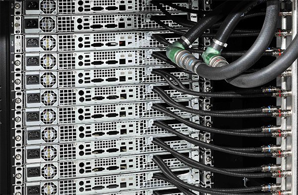
Liquid cooling places hoses, manifolds, pumps, valves, and heat exchangers within inches of high-value servers and electrical equipment. The loss-control issue is not simply whether the coolant is electrically conductive. The review must consider the maximum credible release, its path, exposed equipment, isolation time, and whether unaffected racks retain cooling.
FM Data Sheet 5-32 addresses direct-to-chip, rear-door heat-exchange, and immersion-cooling arrangements. Its loss-prevention approach is to reduce the probability of release, limit the quantity released, keep liquid away from critical equipment, and maintain cooling following a single component failure.[2]
Key loss scenarios include:
-
Hose, fitting, coupling, or manifold failure. A localized release can damage servers, controls, busways, or power distribution equipment. Business interruption may exceed direct damage if multiple racks require shutdown, cleaning, inspection, or replacement.
-
Coolant distribution unit or pump failure. One unit may serve several racks or an entire computing cluster. Failure of the unit, its controls, power supply, or heat-rejection equipment can create a common-mode cooling loss.
-
Failure of automatic isolation. Leak detection has limited value if an alarm does not close the correct valve and limit the release while preserving cooling to unaffected equipment.
-
Loss of cooling during electrical transfer. Pumps, valves, controls, and heat-rejection equipment must be coordinated with emergency power, including transfer time, restart sequence, and available thermal ride-through.
-
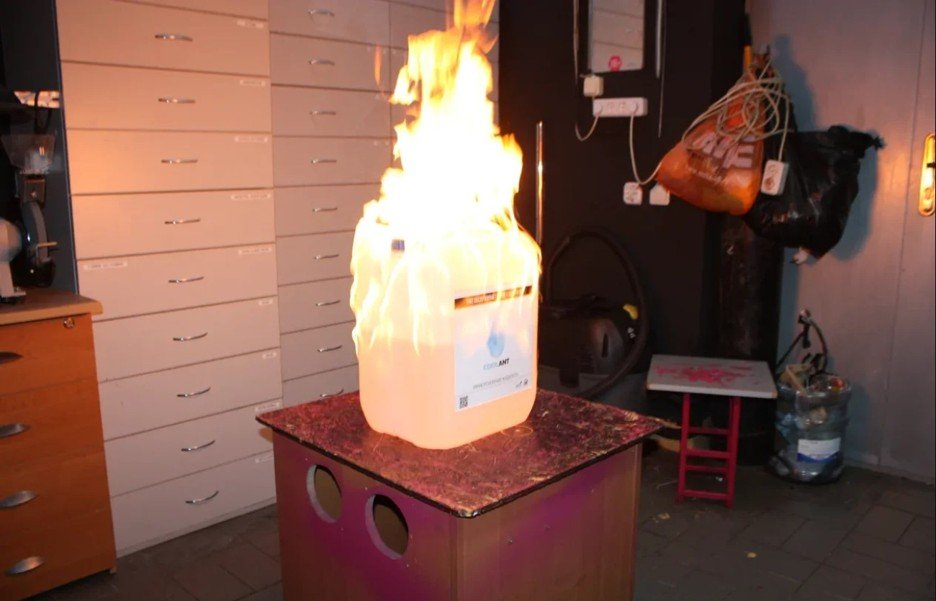
Combustible immersion fluid. A dielectric fluid should not be assumed noncombustible because it is electrically nonconductive. The review should address fire properties, fluid volume, containment, drainage, decomposition products, and representative test data.
Recommended controls include zoned leak detection, supervised isolation valves, drainage or secondary containment, pressure testing, and preventive maintenance for hoses, seals, pumps, heat exchangers, and fittings. The response sequence should identify the affected zone, close the correct valve, notify the operator, and preserve cooling to unaffected equipment. Annunciation alone does not control the loss.
Liquid piping should not be routed above critical electrical or electronic equipment where practical. Where it cannot be avoided, the review should verify shielding, drainage, isolation zoning, joint location, and the potential volume released before isolation.
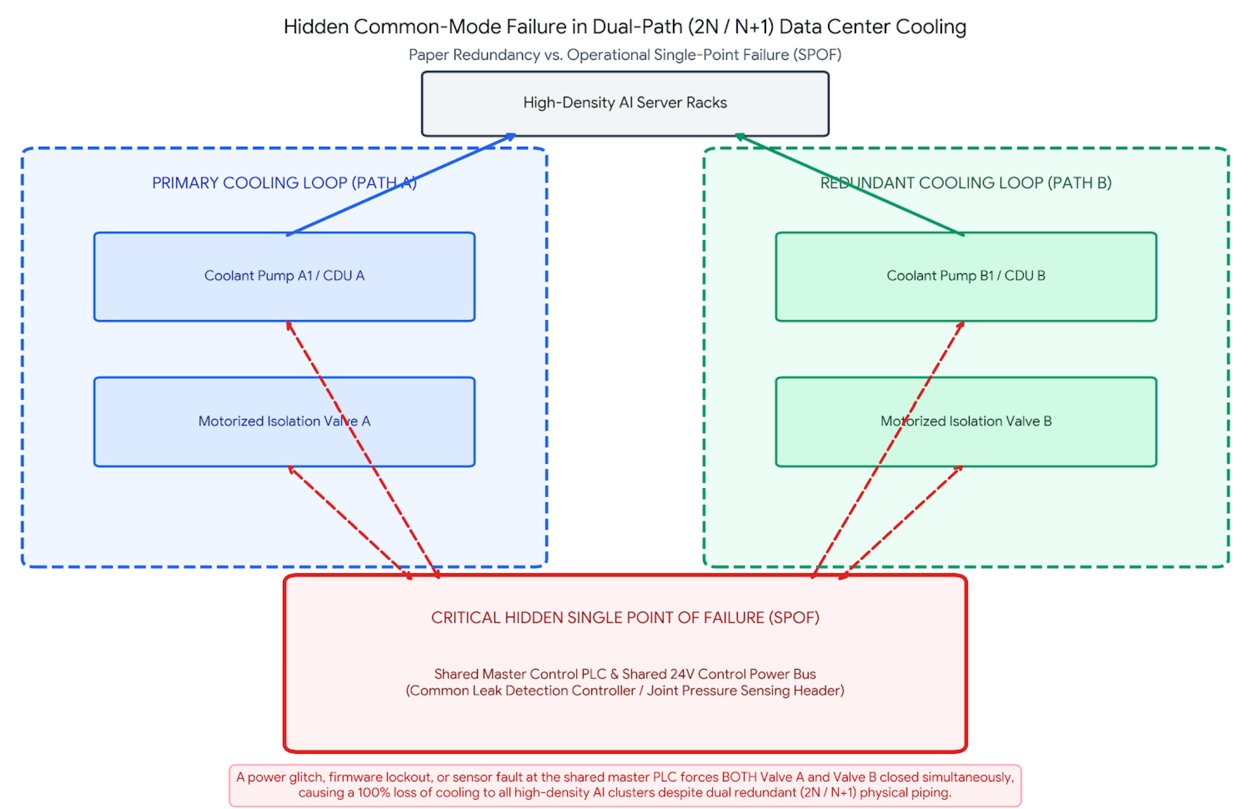
Cooling redundancy must also be evaluated functionally. Two pumps or coolant distribution units may still share one control panel, upstream breaker, common header, heat-rejection loop, or control network. The complete operating path should be traced before accepting an N+1 or 2N designation.
3. Lithium-Ion UPS Systems: Thermal Runaway and Fire Propagation
Lithium-ion UPS systems introduce failure mechanisms that differ substantially from traditional lead-acid arrangements.
Internal defects, electrical abuse, mechanical damage, overheating, or control failures can initiate thermal runaway. The event may release heat and flammable, toxic, and corrosive gases. Depending on the arrangement, consequences can include fire propagation, deflagration, smoke contamination, loss of UPS capacity, re-ignition, and prolonged post-event monitoring.
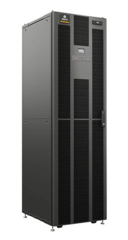
Obtaining the applicable UL 9540A report is only the starting point. The practical question is whether the test represents the installed battery system. Cell chemistry, state of charge, module spacing, cabinet construction, ventilation, protective devices, and suppression conditions should be compared with the field arrangement. A report for a related product family or materially different cabinet should not be treated as proof that the installed configuration will behave the same way.[3]
The review should determine whether propagation extended beyond the initiating cell or module and evaluate heat and gas release, deflagration indicators, re-ignition, and the effects of ventilation, separation, and suppression. A statement that equipment was “tested to UL 9540A” is not a substitute for reviewing the results and limitations.
NFPA 855 provides installation criteria for stationary energy storage systems based on technology, location, size, detection, suppression, ventilation, gas control, and separation.[4] These requirements should be coordinated with FM guidance, equipment listings, manufacturer instructions, and the actual room and cabinet arrangement. For additional detail, see our July 2026 review of notable changes to NFPA 855 affecting stationary energy storage systems.
Off-gas detection can provide warning before visible smoke or full thermal runaway. FM Approvals has approved off-gas detection systems for certain applications, including open data center spaces.[5] The alarm, however, must initiate a defined response. The sequence should address charging shutdown, cabinet isolation, ventilation, evacuation, notification, and emergency escalation.
Clean-agent systems may control exposed flaming combustion but should not be credited with stopping internal battery self-heating. Water-based protection remains important where supported by the design criteria and test data because cooling adjacent cabinets and limiting propagation may be the controlling objective.
Post-event planning is also necessary. Battery temperatures and gas release can remain abnormal after visible fire is controlled, and damaged modules may re-ignite. Procedures should address monitoring, re-entry, removal, temporary storage, contamination control, and restoration of UPS capacity without exposing the remaining system.
4. Fire Protection Must Match the Installed Arrangement
High-density retrofits can leave a facility with fire protection that remains code-compliant on paper but no longer matches the hazard. Higher fan speeds may pull smoke away from sampling points, while new cable trays, busways, piping, and containment panels may obstruct sprinkler discharge or delay heat collection.
Air-sampling smoke detection should be functionally tested with the current airflow and containment configuration in service. Testing should verify sampling-point coverage, transport time, alarm thresholds, annunciation, and transmission to the responsible response location. Moving a sampling point on a drawing is not enough; the revised arrangement should demonstrate detection under representative operating conditions.
Pre-action sprinkler systems require more than confirmation that the valve, detection system, and releasing panel are listed. The review should verify hydraulic adequacy, water-delivery time, sprinkler obstructions, valve supervision, alarm operation, inspection access, and the complete release sequence. It should also confirm that maintenance or loss of control power cannot leave the system unintentionally unavailable. NFPA 13 provides the sprinkler-design baseline, while NFPA 75 addresses fire protection for information technology equipment and areas.[6][7]
Clean-agent systems should be checked against the current room rather than the original commissioning configuration. Changes in cable penetrations, containment, raised-floor openings, HVAC operation, or room volume can affect agent concentration and retention. The review should confirm enclosure integrity, pressure-relief venting, HVAC shutdown, agent distribution, power-isolation logic, and the availability of replacement agent and system components. NFPA 2001 provides the principal design framework.[8]
If the installed agent or equipment cannot be recharged, serviced, or replaced promptly, the facility needs a documented transition plan based on the present hazard and room arrangement. Water-mist systems may be appropriate where listed or approved for the specific application and installed within the tested design envelope. NFPA 750 provides the applicable design and maintenance framework.[9]
For a real-world example of how an electrical fire can affect data center operations, see our analysis of the Hillsboro data center electrical fire.
5. On-Site Power and Shared Hazard Dependencies
Grid constraints and reliability objectives are increasing the use of on-site generation, energy storage, and microgrids. The risk changes when generating equipment moves from intermittent standby service to continuous or extended operation. Longer operating hours increase fuel throughput, maintenance demands, ignition exposure, equipment wear, and dependence on auxiliary systems.
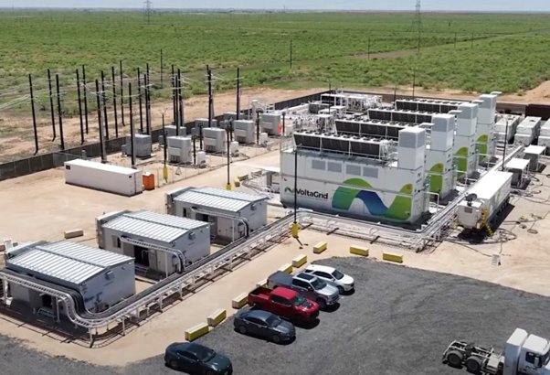
Prime-power installations should be reviewed as industrial utility systems, not oversized standby generators. The review should follow the operating chain from the fuel source through regulators, valves, ventilation, gas detection, emergency shutdown, controls, switchgear, transformers, and cooling auxiliaries. The key question is whether one failure can remove both normal and on-site power.
Nominally diverse sources may still depend on the same switchgear room, transformer yard, gas header, control network, cooling loop, or fire area. The review should confirm physical separation, independent controls, selective electrical protection, emergency isolation, and continued operation during maintenance or a single equipment failure. Shutdown logic should isolate the affected unit without unnecessarily disabling unaffected generation or support systems.
Fire protection should reflect the actual fuel and equipment arrangement. The review should address leak detection, automatic and manual fuel isolation, ventilation, combustible-gas detection where applicable, equipment spacing, drainage, exposure protection, and safe emergency-response access. These provisions should be tested as an operating sequence rather than reviewed only as separate components.
Natural hazards require the same dependency-based review. Redundant generators, cooling towers, or chillers may share the same flood elevation, wind or hail exposure, seismic weakness, or freeze-prone piping route. Outdoor equipment should be evaluated for anchorage, drainage, exposed piping, post-event access, and replacement lead time. A backup system is not resilient when the same event can disable it and the primary system.
6. Management of Change, Commissioning, and Common-Mode Failure
Common-mode failures are often introduced incrementally rather than by one dramatic design error. A new coolant header crosses both data halls. A controls revision places two systems on one network. A battery replacement changes chemistry or cabinet configuration without revisiting ventilation and fire protection. Added cable trays interfere with smoke detection or sprinkler discharge. Each change may appear minor while collectively invalidating the original protection basis.
A formal Management of Change process should identify whether a modification affects leak detection, sprinkler protection, smoke-detection performance, cable loading, firestopping, electrical fault current, protective-device coordination, power isolation, emergency procedures, or the independence of redundant systems.
Enhanced review should be triggered by significant increases in rack density, conversion to liquid cooling, changes in battery chemistry, revised shutdown sequences, increased reliance on on-site generation, or modifications to redundant power and cooling paths. The objective is to identify new common-mode exposure and determine whether existing recommendations remain valid.
Integrated testing should be built around failure scenarios, not only normal startup. A useful test removes normal power, places one side of a redundant system in maintenance bypass, fails a pump or valve, disables a sensor, and verifies what remains available. Testing should confirm interaction among fire and off-gas detection, leak detection, suppression release, pre-action valves, HVAC controls, electrical isolation, UPS systems, emergency generation, cooling transfer, alarm transmission, and operator response. The facility should also demonstrate recovery without creating a second impairment.
Single-line diagrams are necessary, but they do not prove resilience. An N+1 or 2N designation is credible only when the paths are physically separated, functionally independent, testable, maintainable, and recoverable. The final question is straightforward: after one credible fire, liquid release, equipment failure, operator error, control-system event, or natural hazard, what still works?
A practical field review follows the loss across disciplines. For a coolant release, that means tracing the fluid path, electrical exposure, valve response, cooling impact, alarm transmission, and recovery plan. For a battery event, it means tracing gas release, detection, shutdown, ventilation, fire protection, contamination, re-entry, and re-ignition. Hidden dependencies are usually found at these interfaces.
Early plan review can identify conflicts involving fire protection, electrical distribution, cooling systems, Li-ion batteries, UPS/ESS installations, and natural-hazard design before they become embedded in the completed facility.
Engineering Review Priorities
Hazard or Change |
Credible Failure Mode |
Potential Consequence |
Engineering Verification |
|---|---|---|---|
Direct-to-chip cooling |
Hose, fitting, manifold, or coolant distribution unit failure |
Liquid contamination and loss of cluster cooling |
Fluid review, leak detection, isolation, drainage, pressure testing, and maintenance |
Immersion cooling |
Combustible-fluid ignition or tank release |
Fire spread, smoke contamination, and extended outage |
Fluid fire properties, containment, drainage, test data, and suppression compatibility |
Lithium-ion UPS |
Thermal runaway, gas accumulation, propagation, or re-ignition |
Fire, deflagration, smoke damage, and loss of UPS capacity |
UL 9540A review, detection, isolation, ventilation, separation, and automatic protection |
Clean-agent protection |
Inadequate concentration, enclosure leakage, or inability to recharge |
Failure to control fire or prolonged outage following discharge |
Room-integrity testing, agent availability, pressure venting, and isolation sequence |
On-site power |
Fuel release, electrical fault, or common utility failure |
Fire, explosion, or loss of primary and emergency power |
Fuel-system review, separation, shutdown, protection coordination, and dependency analysis |
Material change or high-density retrofit |
Existing protection or redundancy assumptions are no longer valid |
Hidden protection deficiency, inadequate capacity, or common-mode loss |
Management of Change, risk reassessment, updated documentation, and targeted recommissioning |
Conclusion
Data center resilience is established by determining what remains operational after a credible event. A coolant release, battery failure, control fault, or localized fire can escalate when power, cooling, and protection systems share space, controls, utilities, or shutdown/restart logic.
FM Data Sheet 5-32 provides the property-conservation framework, but effective loss prevention depends on site-specific verification of detection, isolation, transfer, shutdown, and recovery sequences. The objective is to prevent one failure from disabling both primary and redundant systems.
Contact Risk Logic
As data centers move toward higher rack densities, liquid cooling, lithium-ion UPS systems, and increasingly complex on-site power infrastructure, traditional loss prevention approaches must evolve with them. Risk Logic provides specialized data center risk engineering, plan review, and property loss prevention services to identify vulnerabilities involving fire protection, electrical distribution, cooling, energy storage, equipment redundancy, and potential common-mode failures.
Contact Risk Logic to discuss your data center risk engineering needs, including site assessments, plan reviews, and site-specific property loss prevention strategies.
References
The editions adopted by the local jurisdiction or required by the insurer may differ from the current editions listed below.
-
PNNL, ASHRAE, and NEMA, AI Data Center Energy Performance Framework, June 2026.
-
FM Property Loss Prevention Data Sheet 5-32, Data Centers and Related Facilities, January 2026.
-
UL 9540A, Standard for Test Method for Evaluating Thermal Runaway Fire Propagation in Battery Energy Storage Systems, applicable edition.
-
NFPA 855, Standard for the Installation of Stationary Energy Storage Systems, 2026 edition.
FM, “What Businesses Should Know About Lithium-Ion Off-Gas Detection,” August 15, 2025.
-
NFPA 13, Standard for the Installation of Sprinkler Systems, 2025 edition.
-
NFPA 75, Standard for the Fire Protection of Information Technology Equipment, 2024 edition.
-
NFPA 2001, Standard on Clean Agent Fire Extinguishing Systems, 2025 edition.
-
NFPA 750, Standard on Water Mist Fire Protection Systems, 2027 edition.